Dalsa Linea Lite line scan camera
The Dalsa Linea line scan camera is parameterized using the setup wizard. This takes over the correct configuration of all camera functions in the background.
Information: The assignment of the inputs and outputs can be found under Hardware/Cameras/Dalsa Linea Lite.
Information: Make sure that the Linea Lite firmware is compatible! An update may be necessary.
Setting up the camera
The camera settings are set automatically by the setup wizard and do not need to be entered in the program management. The setup wizard is started via the "Live image" button of the respective camera station.
To set up, it is best to follow the menu sequence and set up as follows.
Information: Configuration mode must be activated to edit the camera configuration.
Best Practise for first time set up
It is recommended to set up the lens and the camera distance first
-
First start in "Single image with software trigger" mode
-
Configure any lighting inputs
-
Set a rough exposure time. 0.050 to 0.095ms is usually a good starting point
-
Limit image height to 50 to 100 lines to get quick feedback on focus
-
Set the line configuration to "Internal clock" and set the frequency to 1000Hz
-
End setup and start image acquisition with continuous trigger
-
Adjusting the lens and lighting
Once the camera has been mechanically set up, the detailed configuration is carried out
-
Select the correct control mode
-
Select the desired line configuration (rotary encoder or internal frequency)
-
If used, diagnose trigger input in the status line
-
If used, test encoder via diagnostics
-
Test setup with low image height
If the signal sequence works, then specify the correct image height
-
In the "Internal frequency" line configuration, the set value corresponds to the recorded lines per second
-
In the "External encoder" line configuration, the ratio of encoder signals to recorded lines must be calculated.
-
For this purpose, the number of edges per image recording is determined using the rotary encoder diagnostics on track A.
-
The encoder divider can be calculated using the ratio of the number of edges to the desired number of lines.
Warning: To ensure that the image acquisition is always completed, the movement must be longer than the image acquisition of the camera. An excess length of at least 2% is recommended.
Information: Example: Inspection of a round part. 360° correspond to 180,000 edges.
Desired resolution: 8,000 lines (2 images with 4,000 lines each)
Encoder divider: 180,000 / 8,000 = 22.5 -> Rounded up to 23
Calculated backwards, this results in a resolution of 180,000 / 23 = 7826 lines per 360°
For the test, a 15° overshoot is recommended (=187,000 pulses) so that the image acquisition can be completed reliably.
-
Main menu
The main menu contains control functions for setting up and testing the camera. The menu items are activated dynamically depending on the camera's operating mode.
| Menu | Description | |
|---|---|---|

|
Continuous | Starts continuous image capture by triggering one software trigger after the other. This creates the impression of a live image without overloading the system with too many images. |

|
Software Trigger | Triggers a single image acquisition. |

|
Edit configuration | Allows you to edit the camera configuration. |
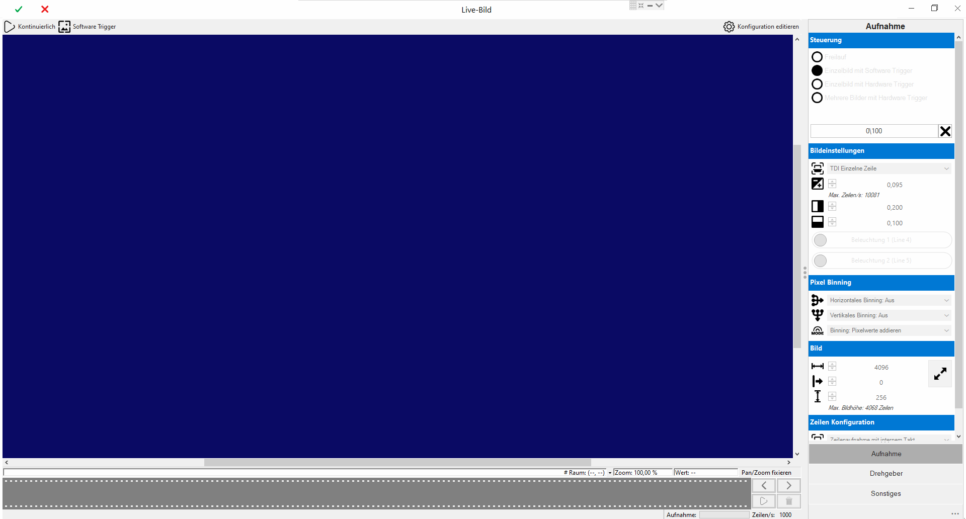
"Acquisition" menu
The basic image recording settings are defined here.
|
|
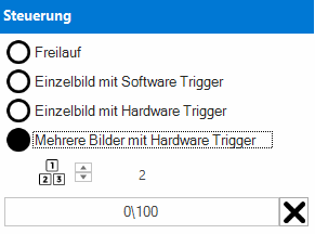
Control | ||

|
Free run |
Images are acquired continuously, one after the other. Particular attention must be paid to system utilisation and acquisition frequency. |
|
|
|
Single image with software trigger |
Captures a single image via software trigger (field bus). |
|
|
|
Single image with hardware trigger |
Captures a single image via camera hardware input. |
|
|
|
Multiple images with hardware trigger |
Captures multiple images (>2) via camera hardware trigger. The images are captured continuously, one after the other. |
|
|
Status display |
Image counter for diagnosing the acquired images. |
||
|
|
Image settings | ||

|
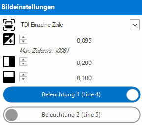
TDI Mode |
Activates the processing of the second hardware line into an output line. |
|

|
Exposure time |
Exposure time in milliseconds. The exposure time limits the maximum number of lines per second. If this specification is exceeded, an image recording error is triggered. |
|

|
Contrast |
Camera contrast (sensor gain) from 0 to 1. A high contrast increases the sensor noise of the image chip, but brightens the image. |
|

|
Brightness |
Camera brightness from 0 to 1. Increases the absolute brightness of the image. |
|
|
Illumination 1 |
Activates the lighting control during image capture. |
||
|
Illumination 2 |
Activates the lighting control during image capture. |
||
|
|
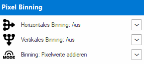
Pixel Binning | ||

|
Horizontales Binning |
Calculates a new pixel from several horizontal pixels. |
|

|
Vertikales Binning |
Calculates a new pixel from several vertical (line) pixels. |
|

|
Modus |
Calculation type with active binning. |
|
|
|
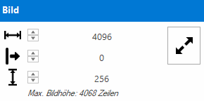
Image | ||

|
Width |
Number of pixels used along the line (camera sensor chip). |
|

|
Horizontal Offset |
Moves the start of the image along the line from left to right. A shift is only possible if the width of the image has been reduced beforehand. |
|

|
Height |
Corresponds to the number of lines to be recorded and is synchronized with the line configuration. Maximum height: 4068 lines per image. |
|
|
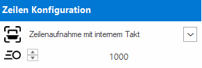
Line configuration | ||
|
|
Line capture |
Switching between external rotary encoder and internal frequency. The input frequency is specified by the encoder configuration. |
|

|
Internal frequency |
Internal frequency in Hz, corresponding to the number of lines per second. |
|
"Encoder" menu
This menu item is only active if the line capture has been set to Encoder.
|
|
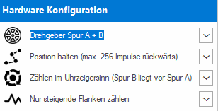
Hardware configuration | ||

|
Encoder |
A track only or with A + B track |
|

|
Mode |
Hold position (observe direction of rotation) or pick up in all directions. |
|

|
Direction of rotation |
Track A is in front of B or track B is in front of A. |
|

|
Edges |
Evaluate only positive or positive and negative edges. |
|
The internally generated encoder pulses are converted into the line input frequency using the encoder divider.
Information: The rotary encoder should be dimensioned so that at least 10 pulses per line are available for conversion.
|
|
Encoder divider | ||

|
Encoder |
Two different operating modes are available for high and low input frequencies. Depending on the mode, the pulses are first multiplied and then divided. |
|

|
Divisor |
Pulses are divided by the divisor. |
|

|
Multiplier |
Impulses are multiplied by the multiplier. |
|
|
Frequency divider |
Specifies the percentage ratio of input pulses and line frequency. The frequency divider is calculated automatically with this specification. |
||
|
|
Encoder diagnostics | ||
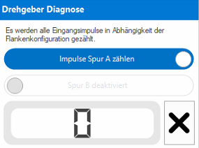
|
Track A |
Activates the pulse / edge counter for track A. |
||
|
Track B |
Activates the pulse / edge counter for track B. |
||
|
Counter |
Number of pulses / edges counted for the selected track. Serves as a set-up aid and test tool when commissioning the encoder for the first time. |
||
"Other" menu
|
|
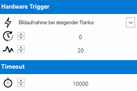
Hardware Trigger | ||

|
Signal |
Edge of the trigger signal used |
|

|
Delay |
Verzögerung des Triggersignales in Mikrosekunden (µs). |
|
|
|
Entprellung |
Debounce time of the trigger signal in microseconds (µs). |
|
| Timeout | |||

|
Image transport |
Timeout for image transport in milliseconds (ms) |
|